model (raster, vector, 2D, 3D, render, animate, simulate, ...) a possible final project, compress your images and videos, and post it on your class page.
Status of the assignments
model (raster, vector, 2D, 3D, render, animate, simulate, ...) a possible final project
compress your images and videos
Post in on your class page
Summary of the week
During my second week I did continue by learning bootstrap package and finalize my www-pages, but also I did install Autodesk Fusion, because it was a new tool for me. I had earlier experiences from Autodesk tinkercard which I have used on my classes with teacher ed students
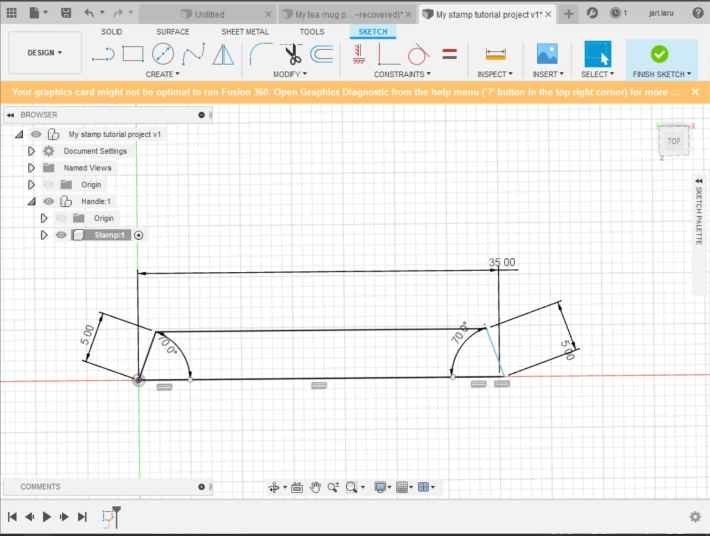
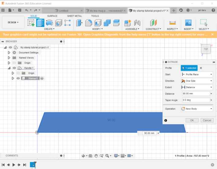
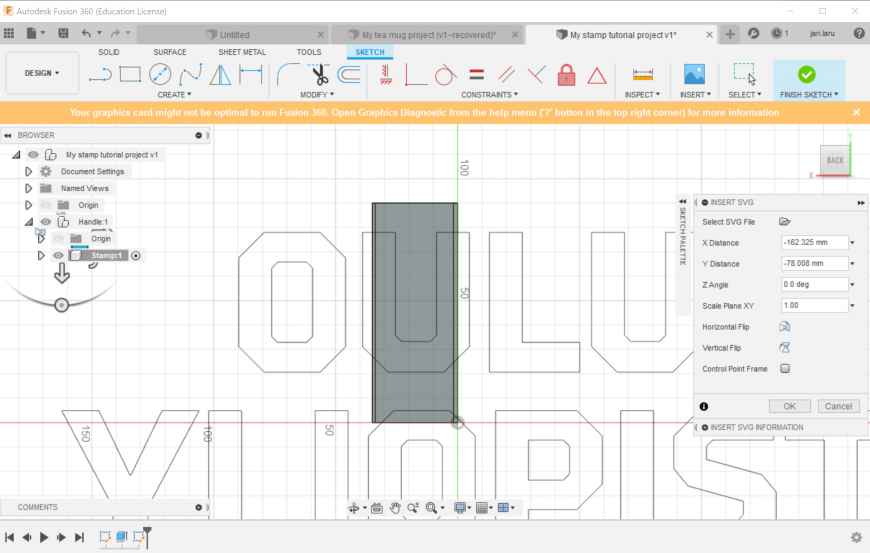
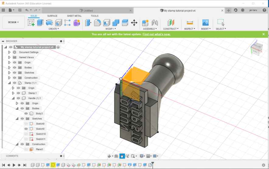
I also did think about my possible final project, but I found good idea just on tuesday, a day before wednesday meeting. So, I decided to do my 3D modelings time to learn basics of Autodesk Fusion. I did two tutorial projects by following Youtube-tutorials: a) Coffee (tea) cup and b) Stamp with handle. That approach was good, because I really did learn how to use software and enjoyed it a lot. I also evaluated how easy it's to learn, because I may use Autodesk fusion on my courses in Teacher Education.
A. 2D design: Inskcape and Gimp
My adventures with Inkspace
Now I am doing this part at the end of the Fab Academy. I haven't got time to finalize my first weeks' documentation before bitter end ;-) So I have got experience a) about documenting, but also b) about Inkscape. However, I still have impression that I am quite beginner with the Inkscape
However, I have used it so far in the context of FabAcademy at lest for following purposes:
This assigment: I did design UI mockup for my final project
In the context of this assignment I did design UI mockup for my final project in Inkscape. UI mockup shows the basic idea for remotecontrol UX of my cardboard RC car. In the design one can regonize controller (left, right, brake and pedal) and two buttons. Auto-button will turn RC car into autonomous mode, where car will drive without controls and "role" -button will add lights and sound to car to turn it into police car
Skills what I did learn in this assigment are more or less related to generic Inscape skills: how to user shortcuts, how to draw and manipulate vector images etc. In the next serie of the pictures you will see how I did design that UI mockup in the practise
Design of the mobile phone
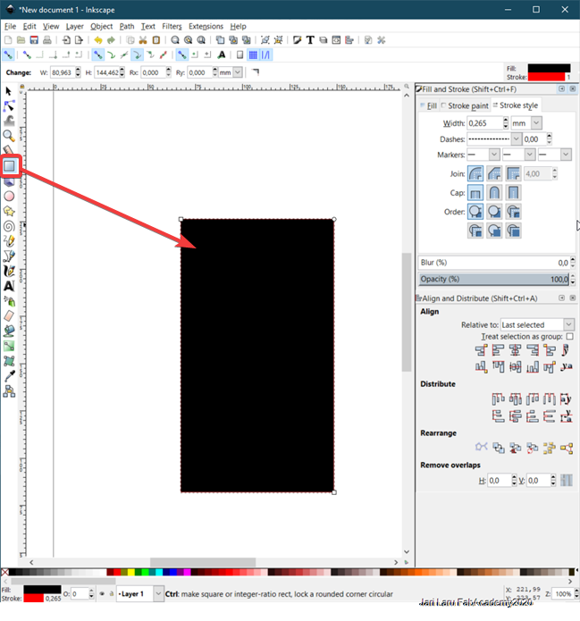
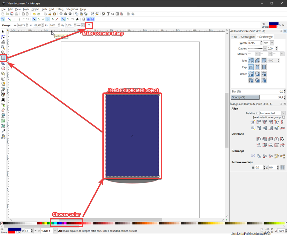
First part of this design process was to design phone as an example of the device where application will be used. I did design rectangle with rounded corners to follow current trends in mobile phones.Next, I did duplicate this square by using keyboard shortcut (ctrl+D).
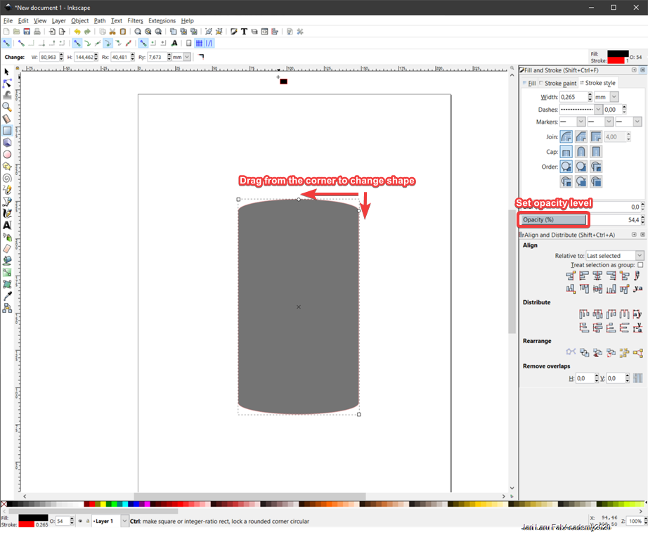
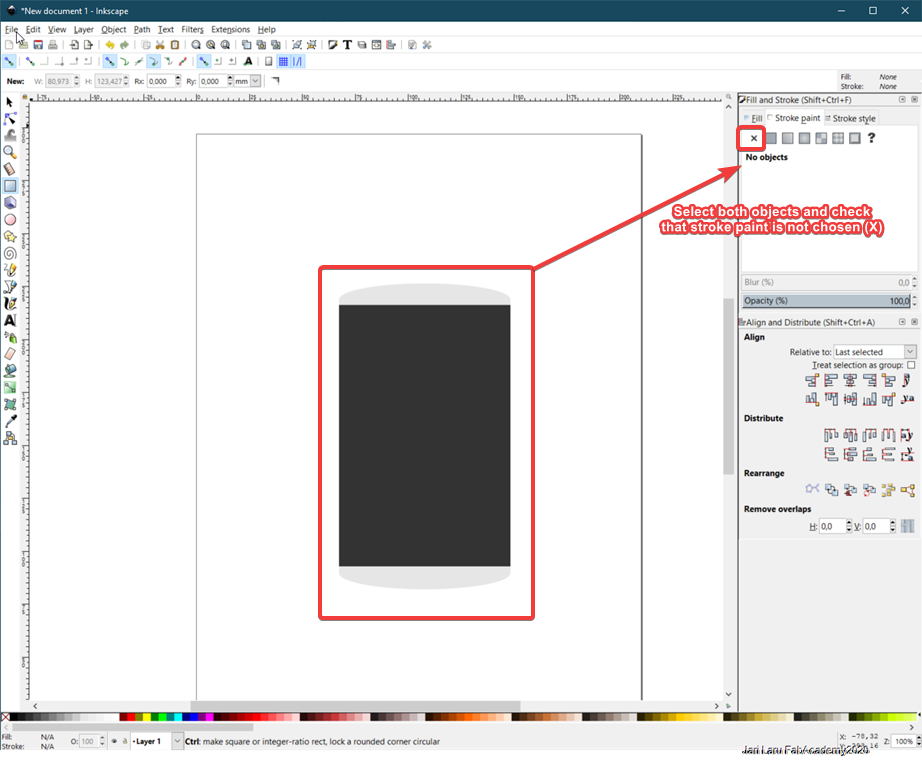
Next, I resized my duplicated object by using handles on the edges of the object. It was done to make space for "home button". Also color was changed into black (from color swatches below the user interface) in order to show the space of the phone display ;). In addition to that, I also removed stroke color in order to get rid of border colors.
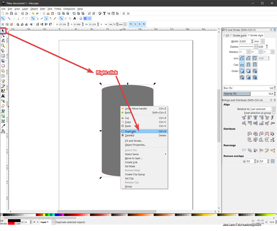
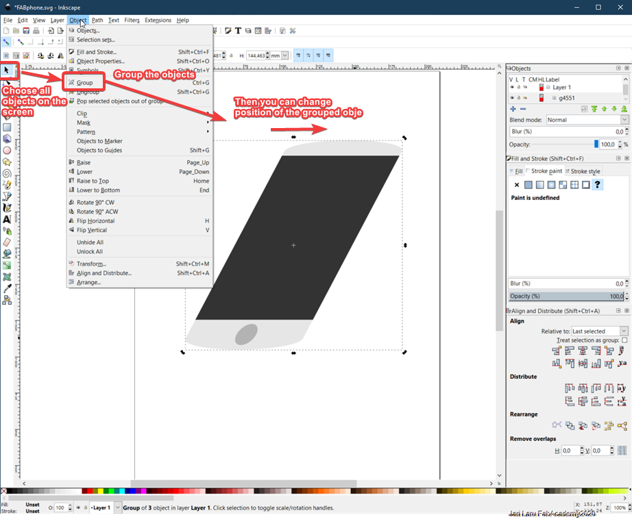
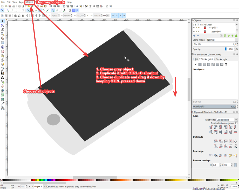
I didc continue by grouping all created objects by selecting them and then using "Object/Group" function from the menu. Then I did changed handles from scale to rotation by clicking object once. Then I was able to change orientation of the phone just dragging handles.
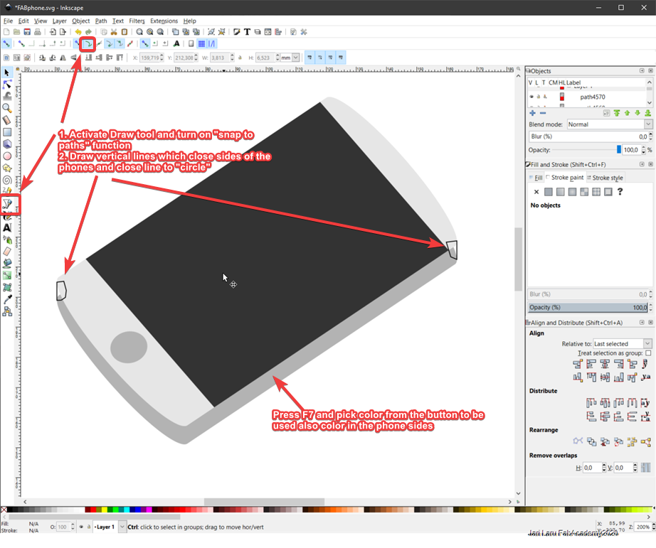
Then I duplicated grouped object and dragged duplicate down by keeping CTRL key pressed. After this I activated drawing tool and snap to paths function from the interface to draw closing lines between original and duplicated phone object.
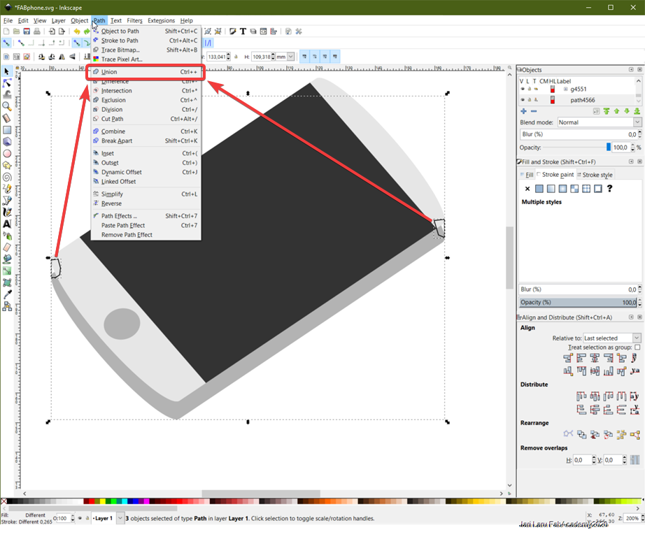
I did draw closed path to both sides of phone and then did combine new drawn objects and earlier duplicated phone form.
Design of the user interface mockup
When phone itself was designed, I started to design application window next to phone. In this moment, I had an idea to have multiple appliction windows organized into top of the phone, but then I noticed time limits and reduced it into one.
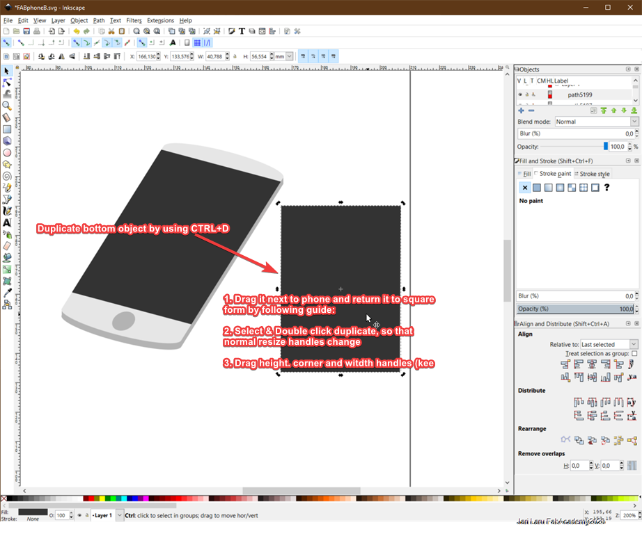
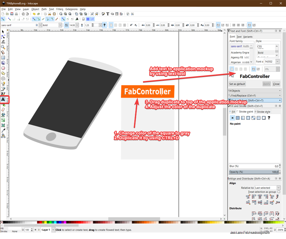
I started this process by duplicating "screen of the phone" and returning it into square position by using rotation handles (click once on top of the object when you have normal scale handles as active).
Next I did change the color of the duplicate to gray (application background) and made again duplicate of this duplicate. I did resize this new duplicate and dragged it into top of the application. You can see it as an orange area with the text of Fab Controller in the image. Text was added by using Text and Font -dialog.
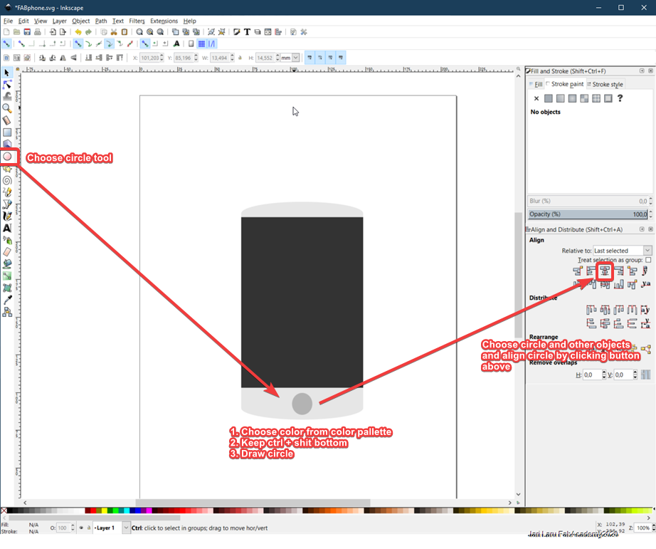
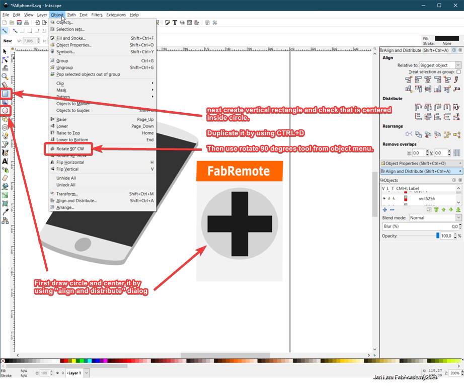
After that I did draw circle (and centered it by using "align and distribute" dialog. Circle will be the background for car controls (left, right, brake and pedal) which will be designed in the next phase.
Next I did draw one rectangle which was centered as above. This rectangle was duplicated and then turned 90 degrees. Then both objects were combined by using "union" -function.
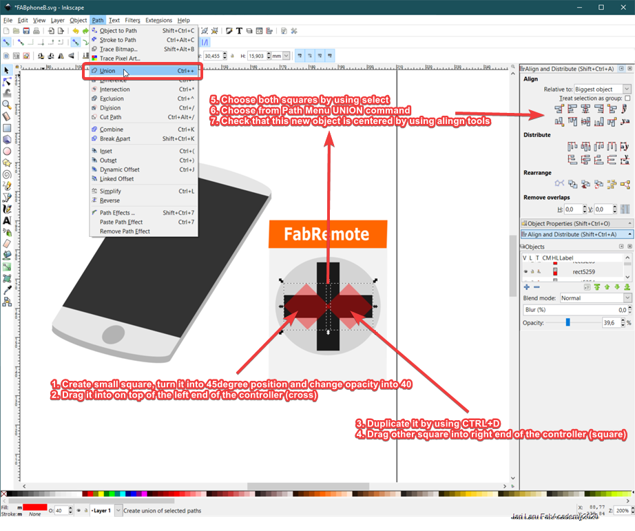
Then I created small square and turned it 45 degrees. Then I placed this object so, that corner of the square was on top of the left edge of the cross.
Next step was to duplicate the object and drag it to opposite direction (right edge). Finally I did combine these together with union and checked alignment with "align and distribute" -dialog
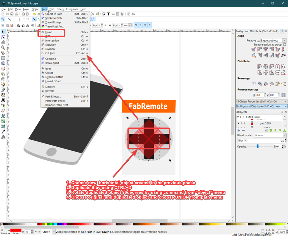
Next step was to select newly created object (two squares) and duplicate it. Then I did turn duplicate 90 degrees as image below illustrates. Now those four squares where combined by using "union" command from paths menu.
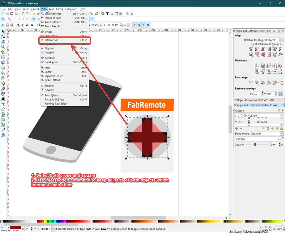
Final step in the designing controller was to intersect parts which are outside of the red square (see figure below). It was done by choosing the cross and square and choosing "intersect" function from paths menu.
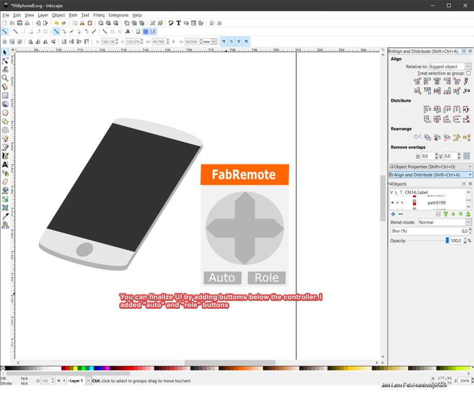
Then I added some buttons below the controller and finetuned colors little bit.
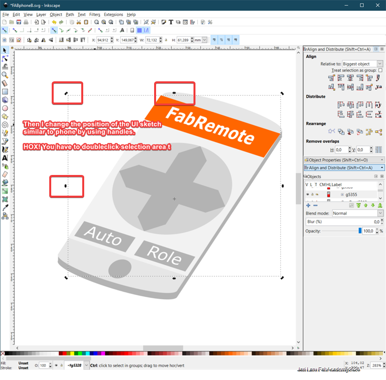
Last thing was to return UI mockup into phone. It was done by choosing the UI mockup object and then clicking on top of chosen object to change "scale" handlers to "rotation handles" and then rotale object to same position than phone screen
Sketching my final project by using Gimp
I used this task to sketch my remote-controlled car project. I am happy owner of Lenovo Yoga laptop with pen, so I started my sketching with the idea of using those functions of my laptop.
Drawing sketch by using Sketchpad
However, path wasnt' so straight than I had imagined. Pen and touchrecognizition technology on my laptop is designed by Wacom and I have used ealier with different programs and use cases, so I thought that Gimp would be similar. It wasn't. I got stuck with input devices configuration without any luck even though I looked through many tutorials
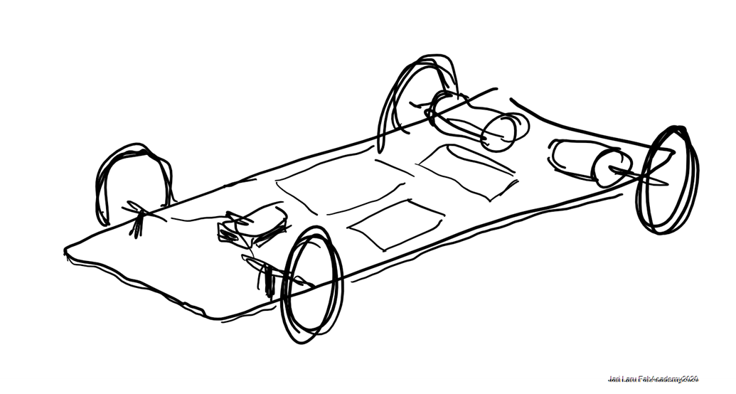
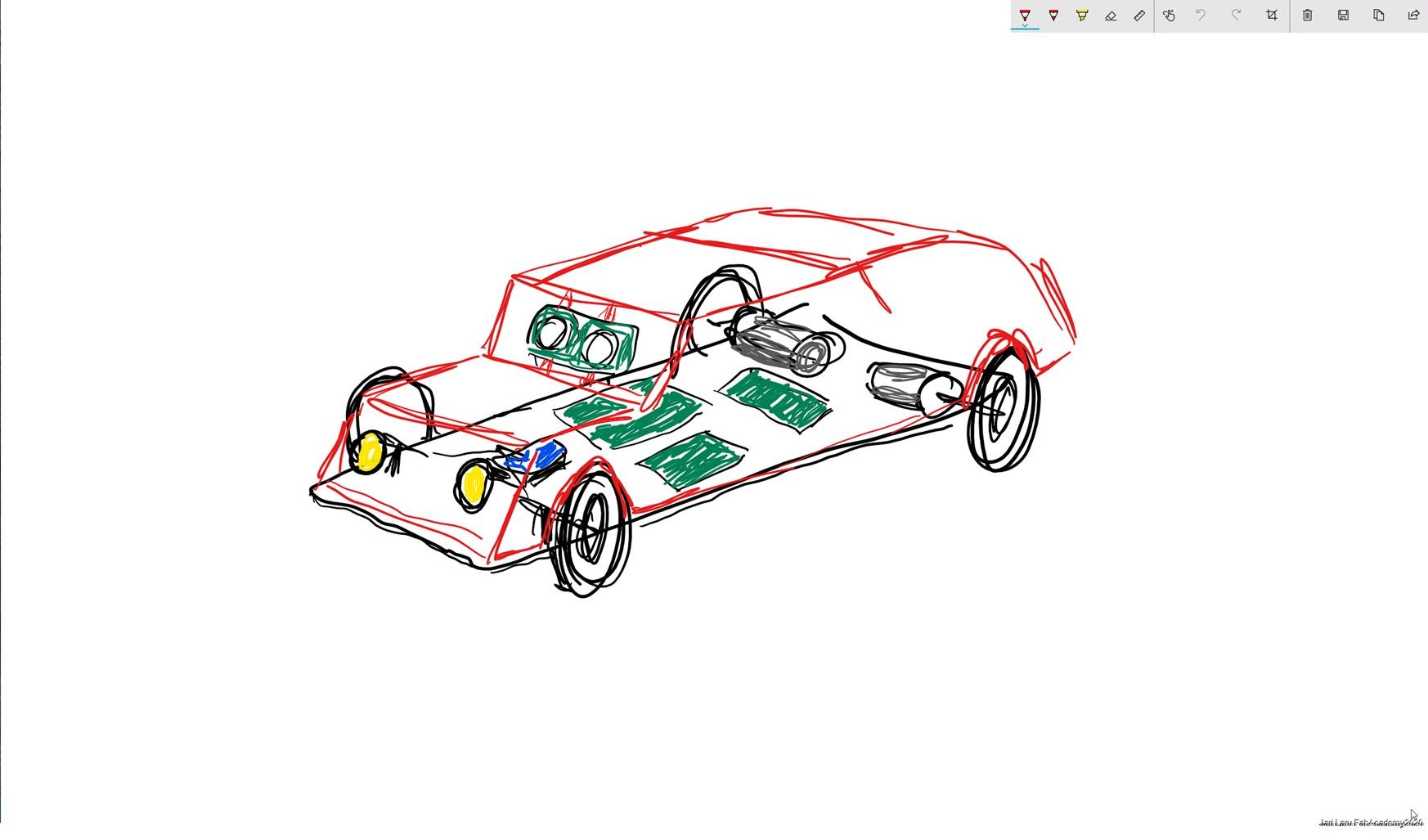
So I had to use plan B to start my sketching. I decided to use simple Sketchpad app on Windows 10 to get fast results. I started with sketching the bottom of the car and then continued with the chassis (red color). You can also see the functions available in the second figure.
When I got hand-drawn sketch I did continue in Gimp. My aim was a) add pictures of the real components into drawing b) name such components and c) to cut car out of the background color and put it into outdoor context.
I did make screenshot by using ShareX screenshot program from SketchPad to continue with same drawing in Gimp.
Continuing with the Gimp
First I did create new image (file/new) in Gimp. I used default settings, because I will anyway grap the ready photo from the screen by using ShareX screen capture tool. In order to start, I did paste drawing from clipboard into Gimp. Don't forget to "click" add new layer when you care pasting from the clipboard into GImp (it will accept pasted layer into list of layers)
Making photos transparent, resizing those and putting then those into correct place
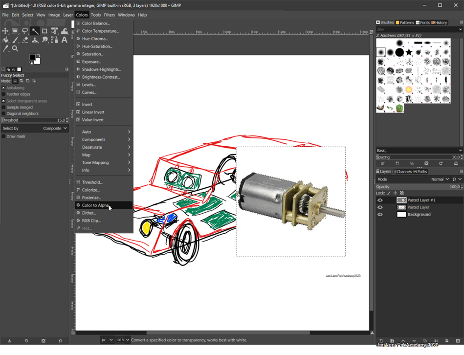
Get photo about component (e.g. micromotor in the figure) and copy it (right click and then copy)
Go to Gimp and use ctrl+v keyboard shortcut to paste photo into Gimp
Accept pasted photo by clicking "add new layer" (bottomright-corner; it's green after paste)
Be sure that your newly created layer has alpha channel (for transparency)
Select "magic wand" tool from the left-menu and use it to new image pasted to Gimp (as photo below shows)
Choose "Colors/Colors to Alpha" from top menubar. Click then ok.
Use scale tool from "Tools/transform tools/scale" (top menubar) to set photo into correct size
Move photo into correct place by using "Move" tool (left menu)
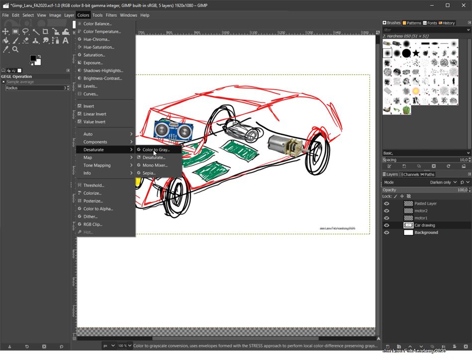
Reducing color palette of the hand-drawn sketch into grayscale colors
In this phase I got the idea to reduce color palette to grayscale colors in order to reduce visual details of drawing
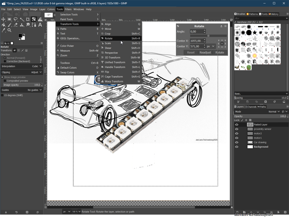
Rotating and cropping the selected object
Some of the photos needed rotating and/or cropping. Example here is neopixel LED bar, which had to both rotate into different angle and crop to fit into car sketch.
In the first photo neopixel bar was rotated by selecting "Tools/transform tools/rotate" from top menubar. (NOTE: if you want your object to be transparent etc. follow guidelines above)
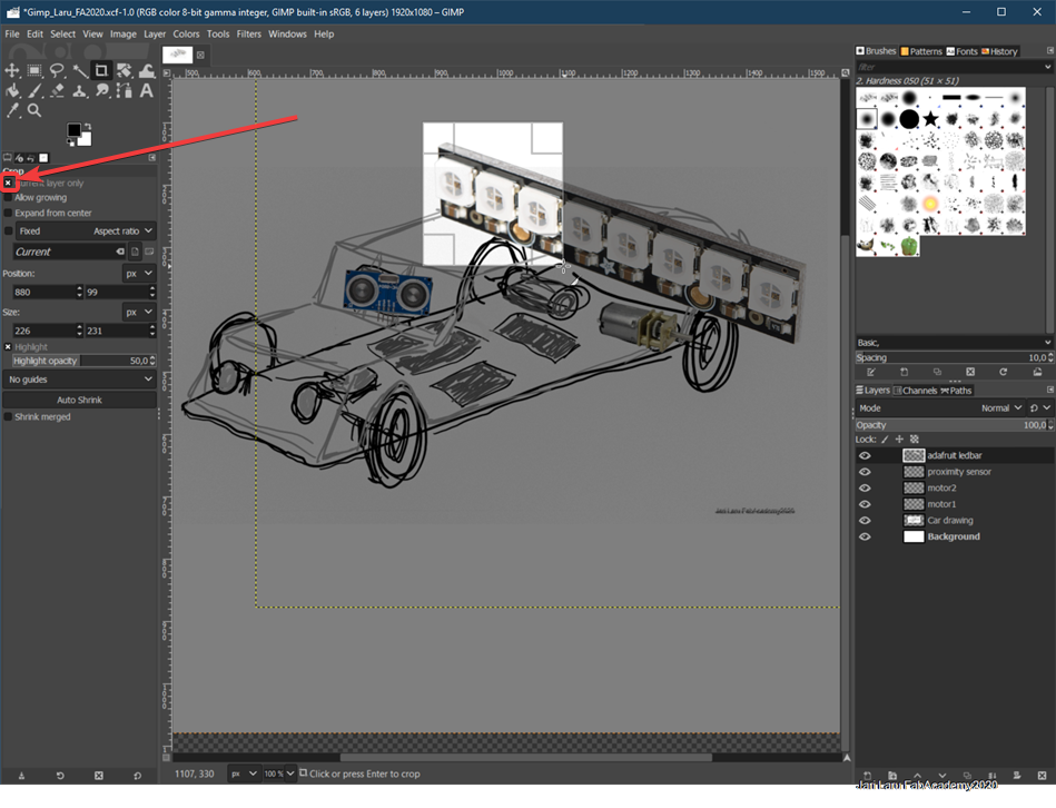
Next I wanted to crop photo (remove unnecessary parts) by using "crop" tool from the left menu. NOTE: be sure that you have selected "current layer only"
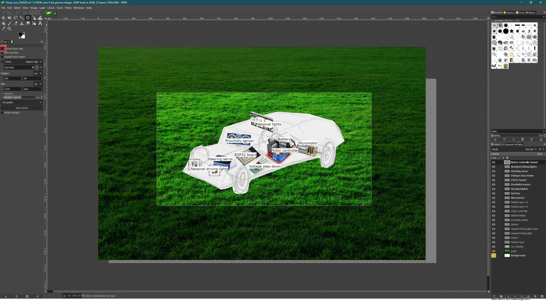
Adding description texts to photos and grassy background
I did continue by adding description texts to each component by using "text-tool" (icon on left toolbar). To make process faster, I did duplicate text layer, dragged it into correct place and then edited it by choosing from layer setting "edit text on canvas"
However, I wasn't happy with transparent background of text box, so I did remove alpha channell from all of text layers. It did remove also possibility to edit text, I don't underatand why, but editing after that change hides text into black box. I thought that it was bug and it wasn't dealbreaker for me, so I did continue forward
Next I wanted to remove white background and replace it with grass photo. It was easy to do with "lasso tool" which is available in the left menu (lasso icon). I just controlled lasso selection by clicking mouse around my sketch. When selection was done working path was similar to earlier workflows above.
Finally it was ready!
Finally it was ready! Last thing left was to crop empty areas of the image off. NOTE: now all layers need to be affected, see the red square on left side of the picture. This setting needs to be unchecked
B. 3D design: my adventures with Autodesk Fusion
As I wrote above, I have limited experiences of doing 3D design: I have used Autodesk Tinkercard with my teacher ed students. Even with TinkerCad I feel my self as a novice.
However, I felt that this assigment was very important step me. It's important, because I have small makerspace in my digital learning lab. It has vinyl cutter, 3D printer (old Prenta) and maybe in the future also entry level Laser cutter. I was very motivated when toying with Autodesk Fusion
Well, I did have very preliminary ideas of final product, e.g. to create boombox or design mobile interface for our IOT-sensors used in science classes, but I wasn't motivated to continue with those ideas to 3D design. Reason for that was the fact, that I did't feel that those ideas would carry on to final products
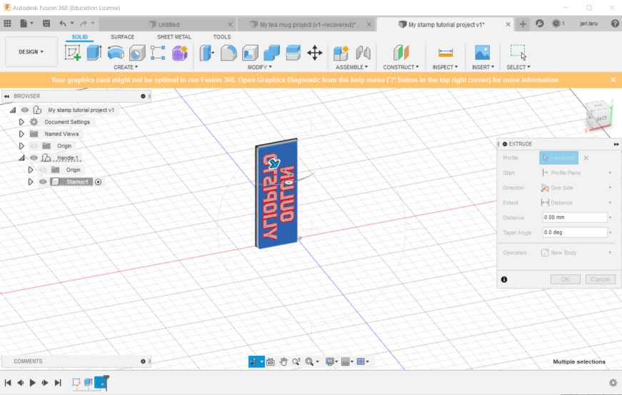
So, in practise, instead of designing prototype of final product, I wanted to learn basics of Autodesk Fusion by following tuorials from Youtube and doing similar kind of products by myself. I will design later on my final product, because I got idea for that just one day ago.
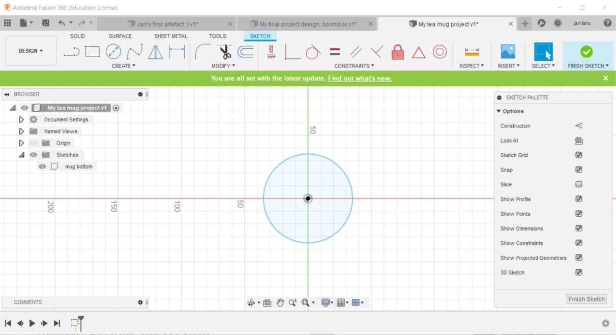
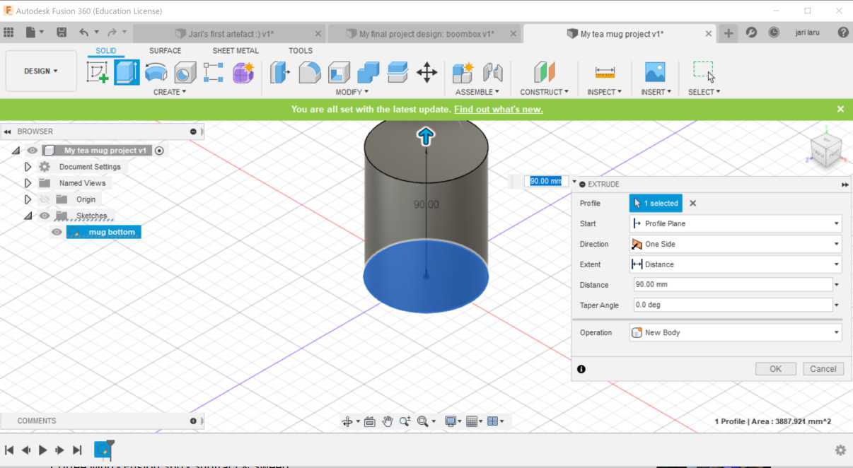
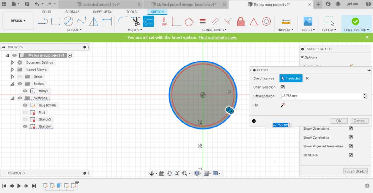
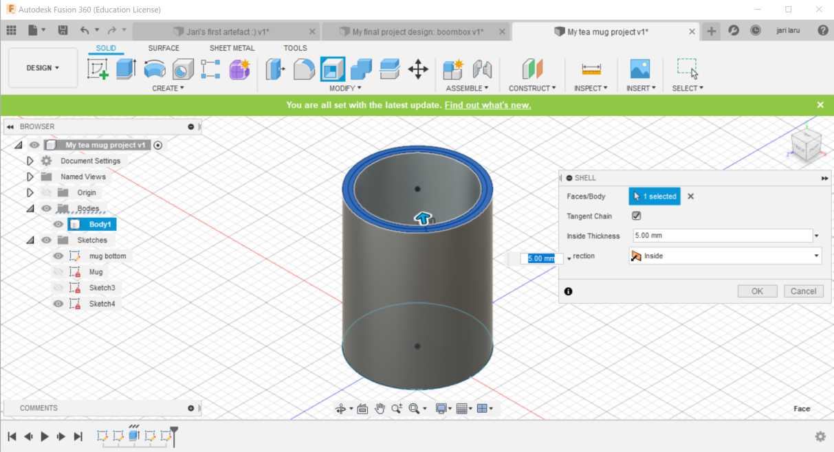
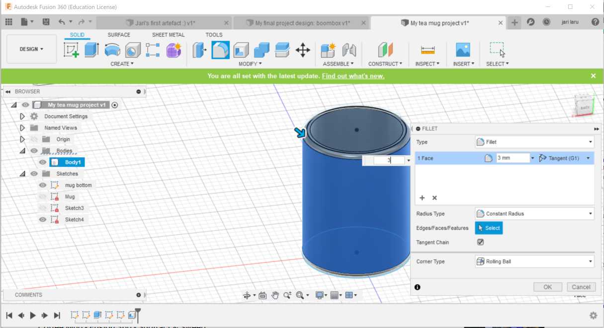
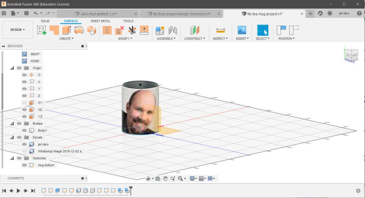
First tutorial video: How to make tea/coffee cup (many videos)
Because my only experiences on 2D and 3D design are from my classes as a teacher education (tinkercad) and from my studies in engineering program years ago (autocad), this was more or less very new phenomena for me. I decided to start from easy exercises by following tutorials. As a first Autodesk Fusion project I picked up "designing a tea cup" :)
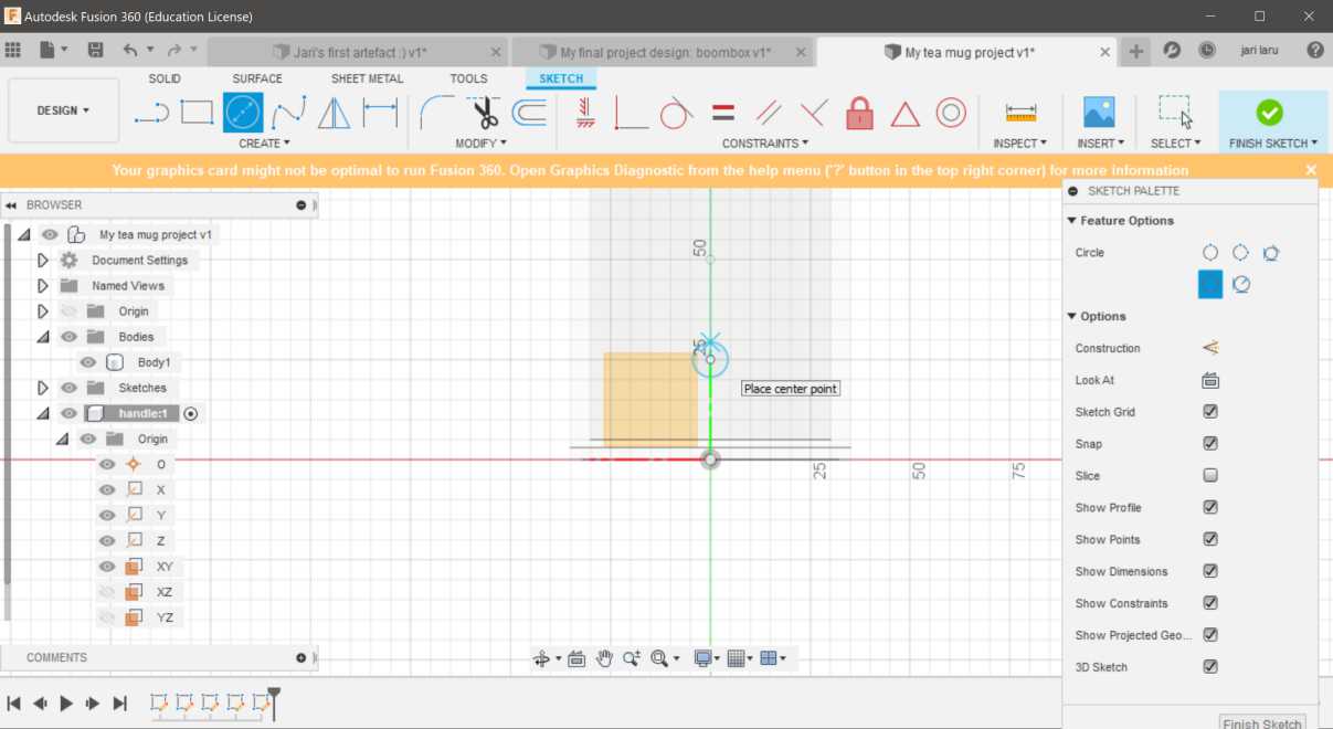
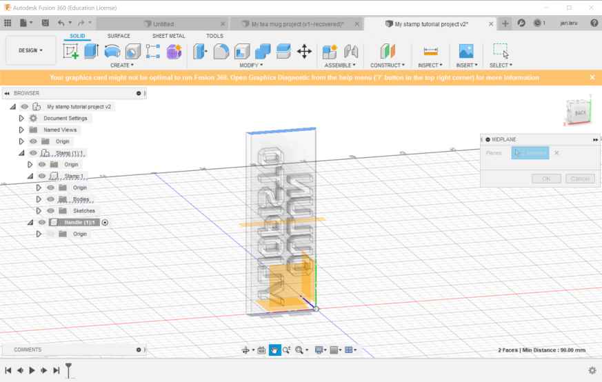
Second tutorial video: Fusion 360 Tutorial for Absolute Beginners
After finalizing my "tea cup exercise", I still had feeling that I need to practise more basics of Autodesk fusion. So, I did continue to second tutorial video: Fusion 360 Tutorial for Absolute Beginners. This was very well done video, which helped me a lot to learn very very basics of the tool.
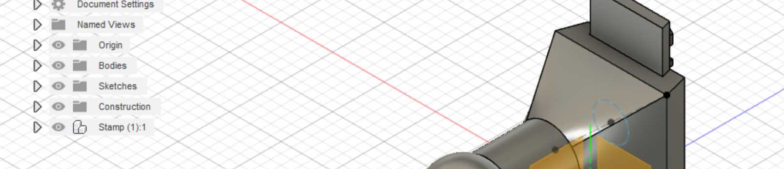
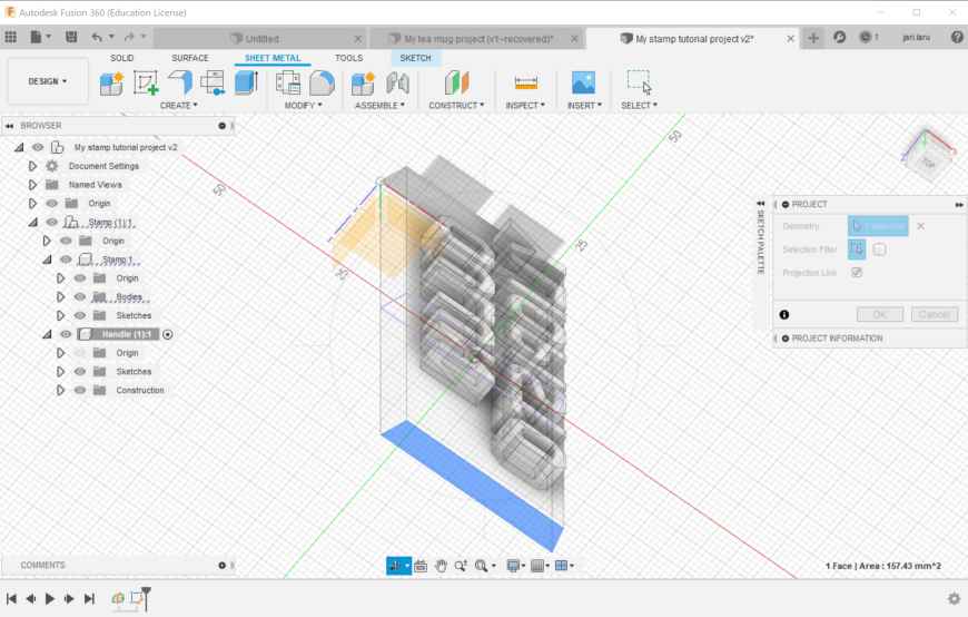
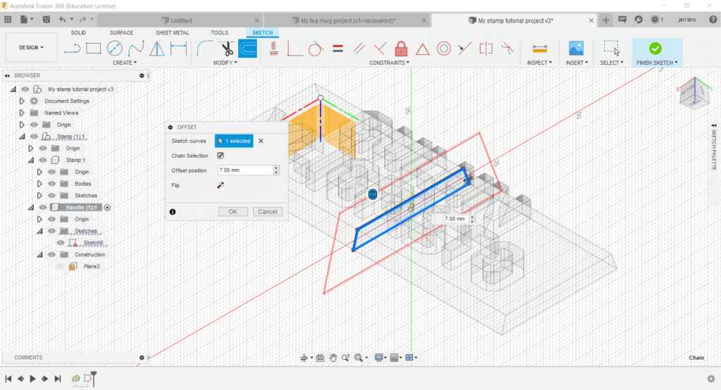
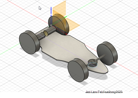
Third Fusion 360 design: very first version of the final project car (mule for fitting boards etc)
This design is very first version of my cardboard RC car. It will be used as a mule for measuring how motors, servos, PCB boards and battery will fit into platform.
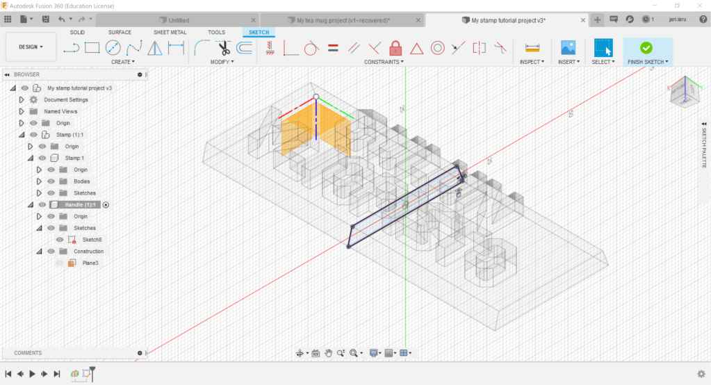
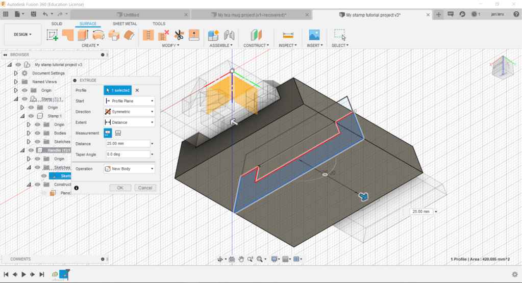
Sketching the body of the car
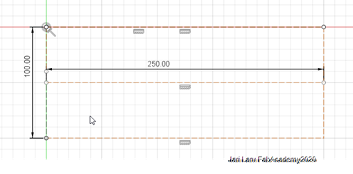
I started by design my sketching a box in the size of the car body (width: 10cm and length 25m [height 2mm cardboard]).All lines in the box are working lines (right click on top of the line and then choose working line), which are guiding the design.
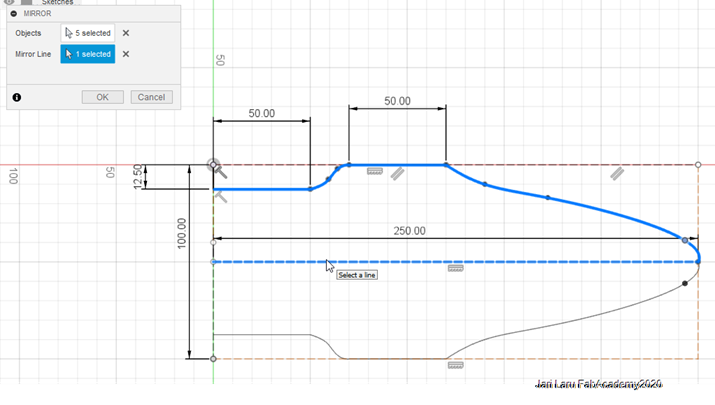
Then I did continue to sketch normal (blue) lines by using both straight line -tool (shortcut L in sketch mode) and fit point spline -tool. Latter is good tool when you need to sketch e.g curves.
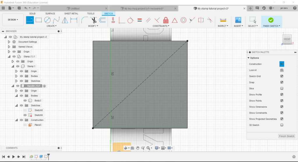
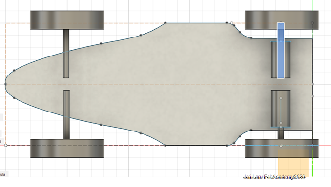
When other side was ready I picked up "mirroring" tool and chose all objects designed in the previous phase. Then I used working line sketched in the middle of the car body as a mirroring line.
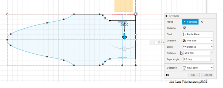
HOX! In the picture below is visible error, which prevents exctrudering. I have forgotten to draw vertical line to the left side of the sketch. I did fix this issue when I found that extrude doesnt work (it needs closed line in sketch)
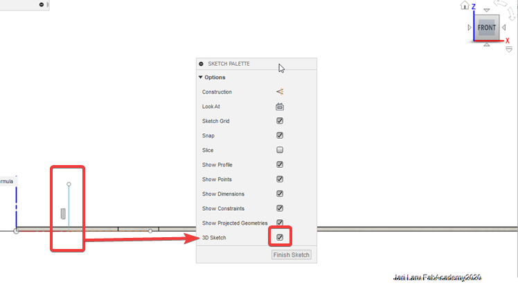
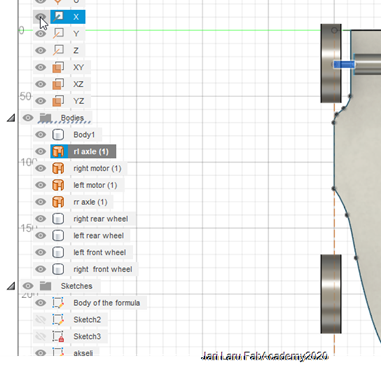
Then I moved to design wheels and axels. I had severe difficulties of invoking sketching in Z axis before I did remember that in my earlier fusion 360 designs I had to close 3D design due to continuous instability issues of Fusion. Now I went to enable it and boom got everything working.
I sketched circle with 10cm diameter and extruded it to have motor. Same thing I made to create axle.
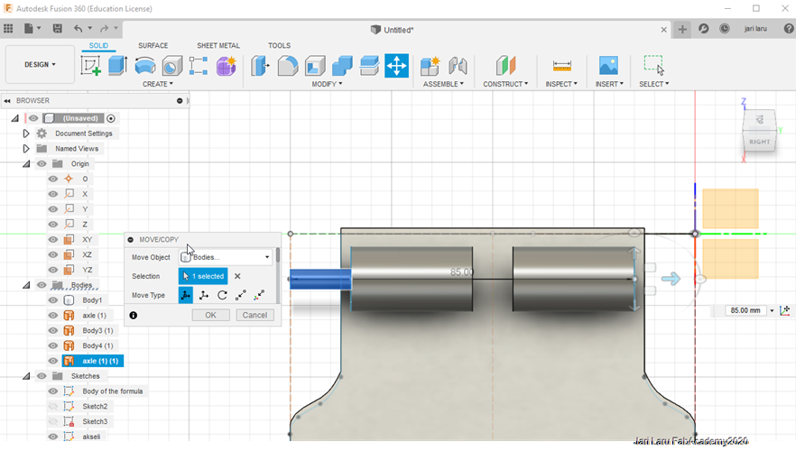
Then I did copy wheels by using dialog (after right click in the respective body) in the left side menubar (bodies)
Then I did change lenght of axels by changin original extrude settings from the history bwroser in the phase where axel was already extruded. Then I did check that all axels are correctly located after that change.
Last thing was to sketch steering into frontaxel. I did sketch simple circle and extrude it to model steering bearings :)
 Reducing color palette of the hand-drawn sketch into grayscale colors
 Rotating and cropping the selected object
 Adding description texts to photos and grassy background


